The Stanley 55 Plane...More Than A Paperweight

If you have just pulled out your Stanley 55 universal hand plane from the depths of the harbor, wipe off the barnacles and find yourself a real boat anchor. There is hope for the good old Stanley 55, and it can be used for its intended purpose as a hand plane to replace a whole tool chest of planes.

 |
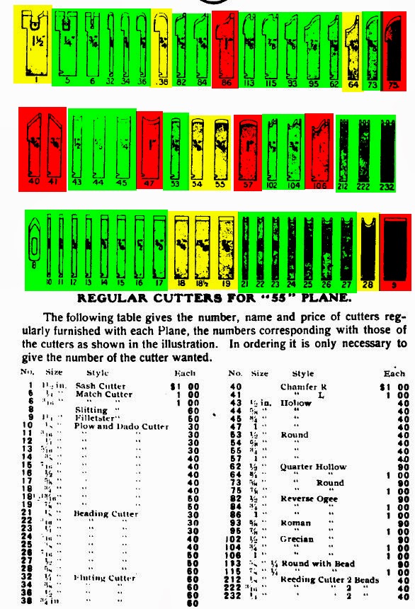
| From the 1934 Stanley Catalog |
Patented in 1894, the Stanley 55 was a prototype contraption of the Victorian era. The "55" was a progression (some would argue a regression) of the Stanley 45. The 45 was patented by Justus A. Traut in 1884. Traut worked with the Stanley Company from 1870 to1908. With over 700 patents to his name, Traut's work left his mark on many of the improvements of Stanley planes which impact us as hand tool users to this day.
 |
| Patent for the Stanley 45 |
 |
| Patent for the Stanley |
In 1893, Eppie McCulloch patented a secondary runner or skate, serving as a bearing surface or sole, that could be adjusted vertically to allow the use of angled or curved cutters.


Traut and Edmund Schade combined the ideas of the 45 and McCulloch's patent ( "Our present invention is in the nature of an improvement upon the inventions shown in Letters Patent No. 294,825, granted to Justus A. Traut March 11, 1884i,V and No. 505,119, granted to Eppie J. McCulloch September 19, 1893.") then added a right sided fence as well as a third runner plus numerous other smaller details to come up with the 55. Production of this plane ceased in 1962.


Stanley claimed that this all-in-one plane can plow, dado, rabbet, filletster, tongue and groove, bead, sash and slit.

Are these claims true?
I believe they are to some degree. This tool shines when using it for short runs of moulding, either for replication of an existing moulding or for a one off new profile. Unless you want to give up your membership to the gym, this tool is not a good choice for making a house full of mouldings. So, the "planing mill" claim is a bit of a hyperbole. Besides its interchangeable cutters and the adjustable steel runner, the feature that sets this plane apart is the presence of dual fences.

Many people who use this plane don't care much for the use of the right sided fence because it is one more thing to set up or the right side of the piece is on their workbench and the fence would bottom out. I agree with what the Stanley instructions say. Use the right fence where possible. If you are making a run of mouldings, try to use a wide board and shape the mouldings with the 55 by placing the board in the vise to work the edge, then cut the moulding off the board. This is easier than ripping the stock to the correct dimension and then trying to clamp the stock in some way. In the event that you do not want to use a wide board working on its edge and are only working with a thin piece, you can lift the piece off the workbench with the modification below.
 |
| The small workpiece is clamped between two notched boards that are secured with T-bolts. The notched boards have small screws with their heads cut off in the notch to grab the workpiece. The workpiece needs to be wider than the notched holding boards to allow clearance of both the right and left fences. |
Alternatively, you can screw or nail both ends of the work to a narrower board which can then be held in your vise. This is my preferred method when working with wider complex mouldings requiring multiple cutters. Essentially, the top face and both edges need to be free of any impediment.

.jpg)
The use of both fences prevents any straying off course of the plane, which is especially important when using profiles that slope down toward the left fence. Have you ever tried to widen a rabbet or groove to house a panel but found the groove to be a bit too narrow? You may have reached for your plow plane and attempted to widen the groove but found that you had inconsistent results. That is why they make side rabbet planes. Alternatively, you can take just a sliver off of a rabbet when using both fences of the 55, staying true to its line. The Stanley 55 instructions mention another method to keep the profile consistent, "By setting up the fence so as to leave a narrow strip of wood between the fence and the cutter...the plane will be much more easily held up to the work." After shaping the profile, you can then remove the small strip of material that served as a fence with a shoulder plane.
If you elect to use only the left fence and want to cinch the stock between two dogs on your workbench, you may run into the problem of not being able to get to the edge of the piece because it is not wide enough to overhang the edge of the workbench. This can be solved by using a sticking board. Here is my version.
 |
| Sticking board variation. The bottom board has two holes to accommodate the T bolts, while the top board/ fence has two slotted holes so that the fence can be adjusted for the width of the stock. Although a bit in the way, if running long stock, the vise can be opened wider to allow the plane to pass through. If creating a bead on the face of the board, the device can be used as a clamp as well. |
 |
| A Lee Valley mortised bench stop. The holes are from screw holes which I sometimes use to buttress the other end of the stock. |
 |
| The board to be "stuck" can overhang the edge a bit. The depth gauge can be referenced off of the fence. |
Once you can setup the work using both fences, you're in good shape. Just try to go with the grain, have sharp cutters, and set your runners for a thin cut.
The thinner cutters work very well. The wider cutters can be a struggle. After sharpening each cutter, I tested it on a short board of pine. Highlighted in green are the cutters that were mostly trouble-free, yellow was a mild struggle (watch the grain direction and take thin passes) and red was tough (chatter and diving of the cutter even with the grain). I have been able to use all of the cutters, but some clean up is needed on the wider cutters.
 |
| When adjusting the runners, point the front of the plane up and sight down along the runners. Always place at least one runner at the lowest point of the cutter. All but a couple of cutters need more than one runner (skate). Adjust the other runners to evenly ditribute them through the width of the cutter. There is also another shoe that attaches to the auxiliary center skate to give more surface area. I have not needed this shoe too often. Note the camera angle grossly exaggerates the exposure of the cutter relative to the runner. |
Here are some of the mouldings using many of the profile cutters:


 |
| Note that some linear marks from the runners can show up when using the larger cutters. These would need to be sanded down or cleaned up with a another plane. |


Besides the shapes provided by the individual cutters, profiles can be combined to create an almost infinite number of possibilities. Even more variety (more than infinite?) can be had by angling the rosewood fence, similar to a spring angle for a wooden moulding plane.
Besides the 55 standard cutters, Stanley made an additional 41 special cutters with more sizes of quarter rounds,hollows, ogees and beading cutters. You can even fashion your own cutters. I made matching quarter round and hollow cutters to create a rule joint for a drop leaf table by reshaping beat up duplicate cutters.
Just discovered your blog today. Been reading it and reviewing for hours now. Great job! Keep em coming!
ReplyDeleteRecently watched the You Ttube video you made demonstrating the Stanley 55 and also went through all your posts in this blog. Awesome. Wanted to thank you for taking the time to share your findings
ReplyDeleteI can't seem to find the video that had the power point presentation I love watching it but can not find it.
ReplyDeleteUnfortnately, that video was presented at the Western PA Woodworkers meeting and our club has decided to allow access only for members.
ReplyDeleteJust obtained a Stanley 55, in great condition in the original box. This is an older model based on the logo design. Would like to date it. Ideas?
ReplyDeleteAssuming that your boxes of cutters match the plane, if it has chamfering cutters, it's post 1925. If the spur/nicker is the adjustable 2 cutter type vs the 3 lobed variety, it is pre mid 1930's. I am afraid I'm not much of an expert on dating...tools or otherwise.
ReplyDelete